Products
- Home
- Products
- Product/technological information
- Damage to Bearings, and its Causes and Remedies
Product/technological information
15. Damage to Bearings, and its Causes and Remedies
Inappropriate handling or use of bearings often results in damage and a shortened life. This section highlights the common causes of trouble and preventative remedies.
| Damage | Damage Symptoms | Cause | Remedy |
|---|---|---|---|
| Flaking | Flaking over the entire circumference on one side of the raceway | Abnormal axial load | Use clearance fit for the outer ring of the non-fixed bearing |
| Ball-pitch flaking on the raceway | Impact load during mounting | Carefully mount the bearing | |
| Rust generated during downtime | Apply rust-proof treatment when a long downtime is scheduled | ||
| Premature flaking on the raceway surface and ball surface (Figure 1) |
Excessive load | Ensure proper load condition | |
| Insufficient clearance | Ensure proper clearance and fitting | ||
| Poor lubrication | Use the correct amount of appropriate lubricant | ||
| Poor mounting | Check the accuracy of the shaft and housing, as well as the mounting method | ||
| Rust | Store and handle with care | ||
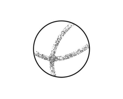
| Flaking inclined toward the raceway (Figure 2) |
Poor mounting and shaft alignment (centering) | Mount and align (center) the bearings properly | |
| Shaft deflection | Select a bearing with a large clearance | ||
| Poor accuracy of shaft and housing | Adjust the perpendicularity of the shaft and housing | ||
| Flaking at the symmetric position of the raceway | Poor housing accuracy | Adjust the accuracy on the surface of the housing bore diameter | |
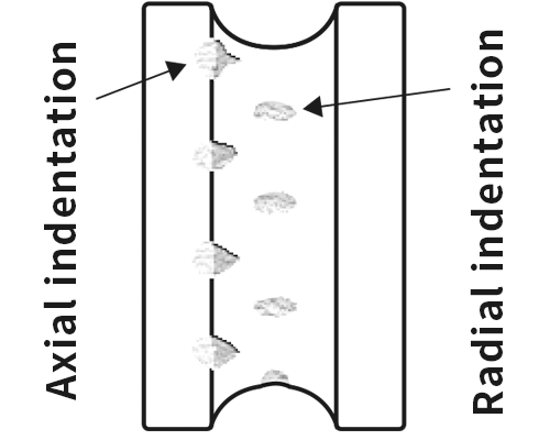
| Indentation | Ball-pitch indentations or dents on the raceway (Figure 3) |
Impact load during mounting or when dropped | Handle with care |
| Excessive load when the bearing is stopped or during low-speed rotation | Check the static load | ||
| Indentation on the raceway and ball surface | Intrusion of sand, metallic dust, etc. | Clean the shaft and housing, and check the sealing device | |
| Seizure | Discoloration of raceway and ball surface | Excessive load | Ensure proper clearance and fitting |
| Insufficient clearance | Ensure proper clearance | ||
| Poor lubrication | Use the correct amount of appropriate lubricant | ||
| Poor mounting | Check the mounting method and relevant components | ||
| Smearing | Softening and adhesion to raceway and ball surface (Figure 4) |
Poor lubrication | Use the correct amount of appropriate lubricant |
| Sliding of balls | Apply proper preload | ||
| Electrolytic corrosion | Corrugated electrolytic corrosion of the raceway (Figure 5) |
Sparking resulting from an electric current passing through the bearing | Ground and/or insulate the bearing |
| Breakage | Cracked or chipped raceway surface (Figure 6) |
Excessive impact load | Apply appropriate load conditions |
| Excessive interference | Ensure proper fitting | ||
| Developed flaking or seizure | Adjust the shaft and sleeve | ||
| Cracked or chipped balls | Excessive impact load | Check the mounting method and load condition | |
| Excessive clearance during use | Check the fitting and bearing clearance | ||
| Broken cage (Figure 7) |
Moment load | Handle with care | |
| Impact due to high-speed and high-acceleration rotation | Check the rotation conditions | ||
| Inappropriate lubrication | Check the lubricant and lubrication methods | ||
| Foreign matter has become entangled | Improve the sealing device | ||
| Galling | Galling on the raceway and ball surface (Figure 8) |
Inappropriate lubrication (solid grease or insufficient grease) | Refill with an appropriate amount of soft grease |
| Heavy acceleration at the start of use (ball slippage) | Avoid sudden acceleration | ||
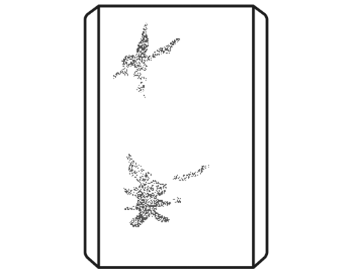
| Wear | Abnormal wear of raceway, balls, and cage (Figure 9) |
Intrusion of foreign matter | Improve the sealing device |
| Rust | Store and handle with care | ||
| Poor lubrication | Use the correct amount of appropriate lubricant | ||
| Galling wear on the fitting surface: creep (Figure 10) |
Insufficient interference | Ensure proper fitting | |
| Insufficient sleeve fastening | Fasten the sleeve appropriately | ||
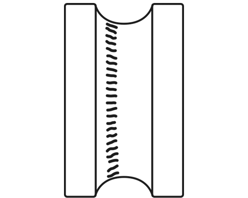
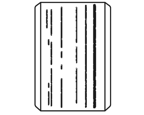
| Red wear on the fitting surface: fretting (Figure 11) |
Small clearance on fitting surface | Increase interference | |
| Ball-pitch fretting on the raceway: false brinelling | Vibrations when the bearing is not used, such as during transportation | Fix the shaft and housing | |
| Rocking movement with a small amplitude | Use oil as lubricant, and apply preload | ||
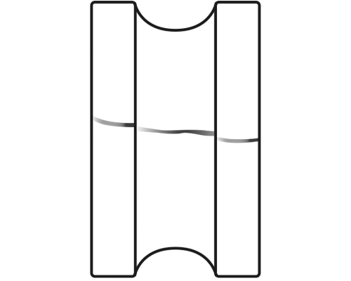
| Rust and corrosion | Rust on the bearing surface and/or within the bearing | Poor storage conditions | Store and handle with care |
| Condensation of moisture contained in air | Store and handle with care | ||
| Rust on fitting surface (Figure 12) |
Fretting | Increase interference | |
| Variable load | Apply oil on the fitting surface | ||
| Corrosion | Intrusion of acid, alkali, or gas | Check the sealing device | |
| Chemical action of lubricant | Check the lubricant |
Flaking
Poor mounting
Indentation
Smearing
Electrolytic corrosion
Crack
Broken cage
Galling
Ball scratches
External creep
Fretting

Rust
Rolling Tracks and How Load is Applied
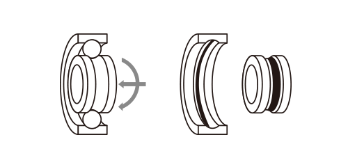
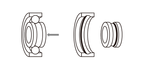
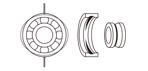
When a bearing rotates with a load applied, the rolling contact between the balls and the bearing rings will generate rolling tracks on the raceway surface of both inner and outer rings. The outline of rolling tracks and how the load is applied can be roughly summarized as shown in the eight figures below. Most of the damage to bearings at an early stage is caused by factors such as unexpected excessive load and mounting errors. Disassembling the bearing and looking at their rolling tracks will enable you to estimate the amount and direction of the load applied as well as the rotating rings, which will provide you with a clue on how to set appropriate load conditions.
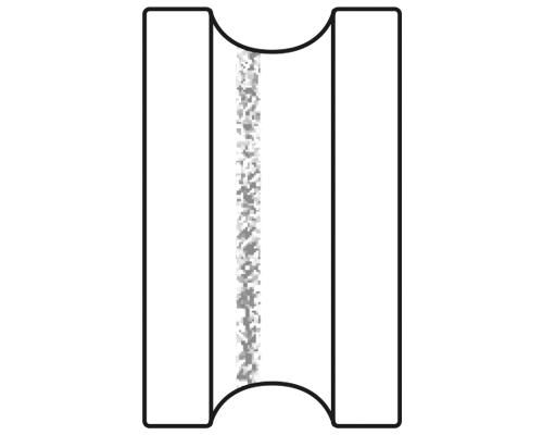
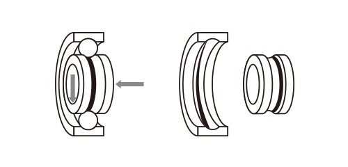
Unidirectional radial load (Inner ring: rotational, and outer ring: static)
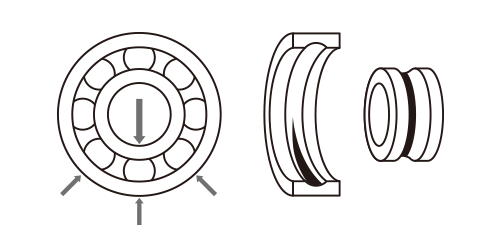
| Inner ring: | The rolling track is observed at the center of the raceway over the entire circumference. The track has an even width throughout. |
|---|---|
| Outer ring: | The rolling track is observed at the center of the raceway. The track is widest in the radial load direction, while it becomes narrower the farther it is from the load direction. |
Unidirectional radial/axial loads (combined load) (Inner ring: rotational, and outer ring: static)
| Inner ring: | The rolling track is deflected to the axial load direction, and is observed over the entire circumference of the raceway surface. The track has an even width throughout. |
|---|---|
| Outer ring: | The rolling track is deflected to and is widest in the axial load direction. This may be observed either over the entire circumference, or just in some parts discontinuously. |
Unidirectional radial load (Inner ring: static, and outer ring: rotational)
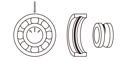
| Inner ring: | The rolling track is observed at the center of the raceway. The track gets widest in the radial load direction, while it becomes narrower the farther it is from the load direction. |
|---|---|
| Outer ring: | The rolling track is observed at the center of the raceway over the entire circumference. The track has an even width throughout. |
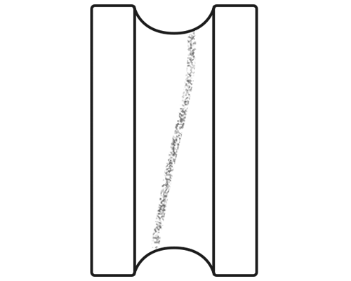
Moment load (Inner ring: rotational, and outer ring: static)
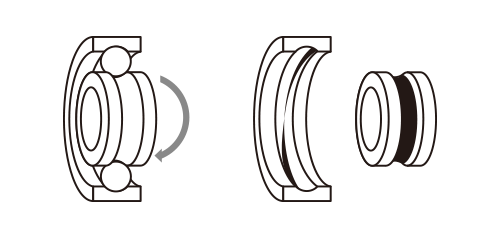
| Inner ring: | The rolling track is observed at the center of the raceway over the entire circumference. The track has an even width throughout. |
|---|---|
| Outer ring: | The rolling track is inclined diagonally with a fluctuating width. |
Unidirectional radial load with radial preload (or negative operating clearance) (Inner ring: rotational, and outer ring: static)
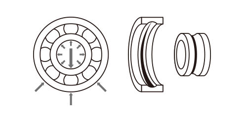
| Inner ring: | The rolling track is observed at the center of the raceway over the entire circumference. The track has an even width throughout. |
|---|---|
| Outer ring: | The rolling track can be observed at the center of the raceway either over the entire circumference, or just in some parts discontinuously. The track is widest in the radial load direction. |
Axial load and moment load (Inner ring: rotational, and outer ring: static)
| Inner ring: | The rolling track is deflected to the axial load direction, and is observed over the entire circumference of the raceway surface. The track has an even width throughout. |
|---|---|
| Outer ring: | The rolling track is deflected to the axial load direction and is inclined diagonally, and is observed over the entire circumference of the raceway surface. The track has an even width throughout. |
Unidirectional axial load (Inner ring: rotational, and/or outer ring: rotational)
| Inner ring: | The rolling track is deflected to the axial load direction, and is observed over the entire circumference of the raceway surface. The track has an even width throughout. |
|---|---|
| Outer ring: | The rolling track is deflected to the axial load direction, and is observed over the entire circumference of the raceway surface. The track has an even width throughout. |
When the outer ring is deformed to oval shape (Inner ring: rotational, and outer ring: static)
| Inner ring: | The rolling track is observed at the center of the raceway over the entire circumference. The track has an even width throughout. |
|---|---|
| Outer ring: | The rolling track is widest where the raceway is compressed. The length in the circumferential direction changes depending on the amount of deformation and the bearing’s initial radial internal clearance. |