Products
- Home
- Products
- Product/technological information
- Internal Clearance of Bearings
Product/technological information
8. Internal Clearance of Bearings
Internal Clearance and Standard Values
Internal Clearance of Bearings
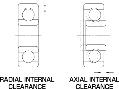
Internal clearance is the space among a bearing’s outer ring, inner ring, and balls. Generally speaking, the amount of vertical movement of the outer ring with the inner ring fixed is called the “radial internal clearance,” and the amount of horizontal movement is called the “axial internal clearance.” The amount of internal clearance during the bearing’s operation is an important factor that impacts performance such as noise, vibration, heat generation, and fatigue life.
Deep groove ball bearings are usually classified by their radial internal clearance. In the actual clearance measurement, a designated load is applied to achieve stable results. As elastic deformation of the bearing occurs during the measurement, which makes the results larger than the true clearance, a correction (reduction) is made to obtain the true clearance.
Radial internal clearance of small/miniature bearings
| Clearance symbol | MC1 | MC2 | MC3 | MC4 | MC5 | MC6 | |
|---|---|---|---|---|---|---|---|
| Clearance | Minimum | 0 | 3 | 5 | 8 | 13 | 20 |
| Maximum | 5 | 8 | 10 | 13 | 20 | 28 | |
Remarks:
- Standard clearance is MC3.
- The correction in the following table should be made when using the values above as measurement clearance.
| Clearance symbol | MC1 | MC2 | MC3 | MC4 | MC5 | MC6 |
|---|---|---|---|---|---|---|
| Correction | 1 | 1 | 1 | 1 | 2 | 2 |
Remarks: The measurement load is:
- For miniature bearings ... 2.5N(0.25kgf)
- For small bearings ...4.4N(0.45kgf)
Radial internal clearance of standard deep groove ball bearings
| Nominal bearing bore diameter d(mm) | Radial internal clearance | |||||
|---|---|---|---|---|---|---|
| More than | Or less | C2 | C0 | C3 | C4 | C5 |
| 2.5 | 6 | 0-7 | 2-13 | 8-23 | 14-29 | 20-37 |
| 6 | 10 | 0-7 | 2-13 | 8-23 | 14-29 | 20-37 |
| 10 | 18 | 0-9 | 3-18 | 11-25 | 18-33 | 25-45 |
| 18 | 24 | 0-10 | 5-20 | 13-28 | 20-36 | 28-48 |
| 24 | 30 | 1-11 | 5-20 | 13-28 | 23-41 | 30-53 |
| 30 | 40 | 1-11 | 6-20 | 15-33 | 28-46 | 40-64 |
| 40 | 50 | 1-11 | 6-23 | 18-36 | 30-51 | 45-73 |
| 50 | 65 | 1-15 | 8-28 | 23-43 | 38-61 | 55-90 |
| 65 | 80 | 1-15 | 10-30 | 25-51 | 46-71 | 65-105 |
| 80 | 100 | 1-18 | 12-36 | 30-58 | 53-84 | 75-120 |
| Nominal bearing bore diameter d (mm) | Measurement load | Clearance correction (μm) | ||||||
|---|---|---|---|---|---|---|---|---|
| C2 | C0 | C3 | C4 | C5 | ||||
| More than | Or less | N (kgf) | Min. | Max. | Common | Common | Common | Common |
| 2.5 | 18 | 24.5(2.6) | 3 | 4 | 4 | 4 | 4 | 4 |
| 18 | 50 | 49(5) | 4 | 5 | 6 | 6 | 6 | 6 |
| 50 | 80 | 147(15) | 6 | 8 | 8 | 9 | 9 | 9 |
Remarks:
- Standard clearance is C0.
- Corrections in the table above should be made when using the values above as measurement clearances.
- For the correction of C2 clearance, be sure to apply the minimum values to minimum clearance, and the maximum values to maximum clearance.
Relation between Radial Internal Clearance and Axial Internal Clearance
The axial internal clearance is determined based on the values of ball diameter, inner/outer ring raceway radius, and radial internal clearance. It is risky to select a bearing with a small radial internal clearance or a fitting with a large interference with the aim of achieving a smaller axial internal clearance after mounting.
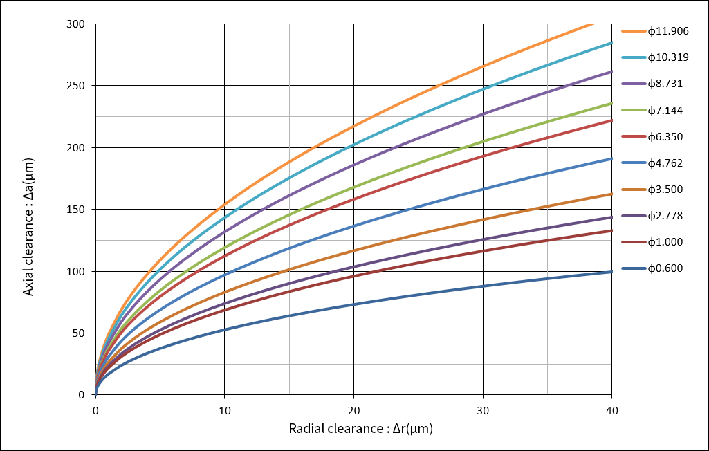
Correlation between radial clearance and axial clearance according to ball diameter
Δa≒2×(Δr×(ro+ri-Dw))0.5
Δa=Axial internal clearance (mm)
Δr=Radial internal clearance (mm)
Dw=Ball diameter (mm)
ro=Outer ring raceway radius (mm)
ri=Inner ring raceway radius (mm)
Selection of Bearing Clearance
Theoretically, the longest bearing life can be achieved by setting the clearance during operation to a slightly negative value. However, it is also known that the life becomes significantly shorter when the negative clearance exceeds this value, even to the slightest degree. Therefore, normal practice is to select an initial clearance so that it becomes slightly positive (away from zero). Generally, MC3 is selected for miniature/small bearings, and C0 is selected for standard bearings.
Selection criteria for radial internal clearance
| Conditions of use | Selected clearance |
|---|---|
| Clearance fit is used for both inner and outer rings; small axial load; rigidity in the axial direction is not required; clearance should be reduced without applying preload; vibration and noise should be reduced; and low-speed rotation. | MC1, MC2 and C2 |
| Friction torque should be decreased; normal axial load; normal rigidity in the axial direction; slight interference fit is used for the inner ring, and clearance fit is used for the outer ring; and mid- and low-speed rotation. | MC3, MC4 and C0 |
| Friction torque should be made particularly small; large axial load; rigidity in the axial direction is required; heavy load or impact load that requires interference; the inner ring’s temperature is high, or the outer ring’s temperature is low; and large shaft deflection. | MC5, MC6, C3, C4 and C5 |
Relation between Radial Internal Clearance and Angular Clearance
During the actual use of a bearing, it may receive a moment load as a result of factors such as shaft deflection due to load and the housing’s cylindricity. At this time, an inclination called the “angular clearance” is generated at the inner and outer rings. If the allowable angular clearance determined for each bearing is exceeded, this may cause an abnormal stress between the raceway and the ball, which will result in high temperatures or flaking.
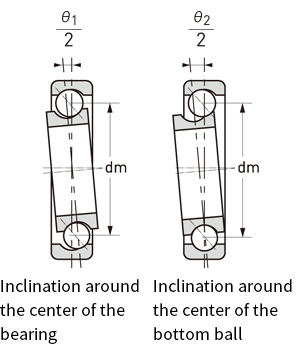
Angular clearance refers to an angle that may be freely inclined when either the inner or outer ring is fixed, and when the ring that is not fixed is tilted to the left or right. The inclination around the center of the bearing is defined as θ1, and the inclination around the center of the bottom ball is defined as θ2. θ1 is significantly larger than θ2. The angular clearance must be taken into account when designing the device and installing the bearing.
θ1=2×tan-1 (2×(Δr×(ro+ri-Dw)) 0.5/dm)
θ2=2×tan-1((Δr×(ro+ri-Dw)) 0.5/dm)
θ1=Angular clearance around the center of the bearing
θ2=Angular clearance around the center of the bottom ball
dm=Pitch circle diameter (mm); generally dm = (D+d)/2
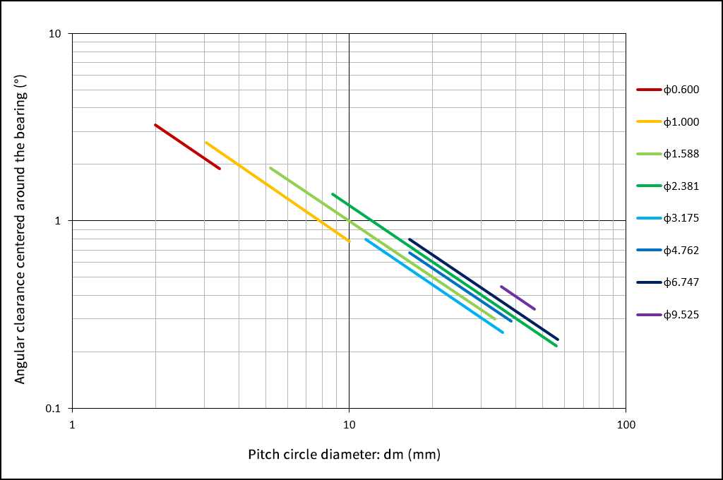
Pitch circle diameter and angular clearance according to ball diameter
Calculation of Clearance
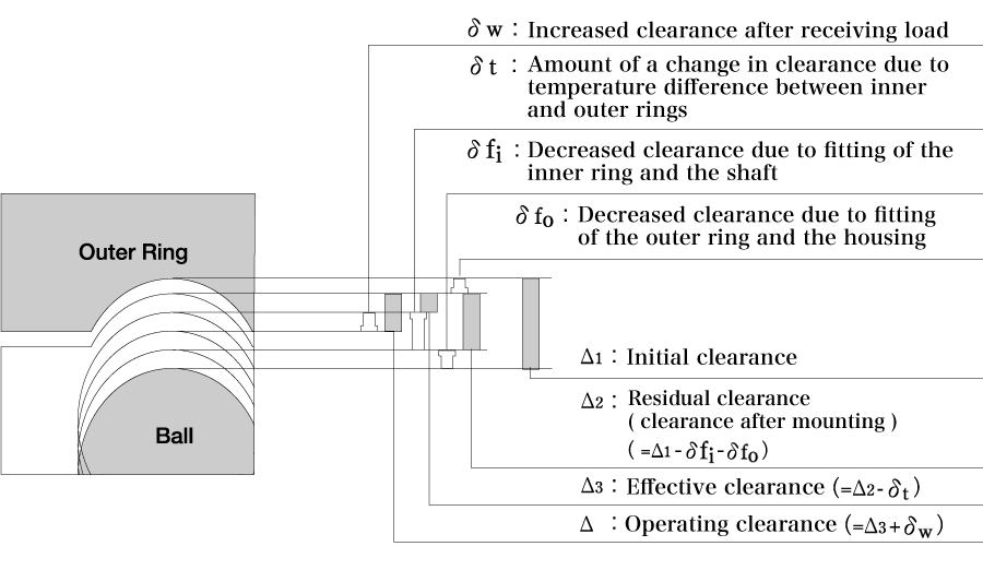
(1) Operating clearance: Δ
Operating clearance refers to a clearance with elastic deformation caused by load and fitting during bearing operation at a constant temperature.
Δ=Δ1- (δt+δf) +δw (mm)
(2) Decreased clearance due to temperature difference between inner and outer rings: δt
Under normal operating conditions, the balls will have the highest temperature, followed by the inner ring, with the outer ring at the lowest temperature. It is difficult to measure the temperature of the balls, which is deemed to be identical to that of the inner ring for the sake of practical convenience.
δt≒a×ΔT×Da (mm)
(3) Decreased clearance due to fitting: δf
When the bearing is mounted on a shaft or the housing with interference, the outer ring will contract, while the inner ring will expand, resulting in a decrease in the bearing’s internal clearance.
δf=δfi+δfo=Δdb×d/db× ((1-(do/d)2)/(1-(do/db)2)) +ΔDa×Da/D× ((1-(D/Dh)2)/(1-(Da/Dh)2)) (mm)
(4) Increased clearance after receiving load: δw
When a load is applied to the bearing, the internal clearance increases due to elastic deformation.
δw=C× ((0.51×Fr)/(Z×cosα)) (2/3)×(1/Dw)(2/3)(mm)
The contact angle α at this time can be obtained by the following equation:
cosαo/cosα=1+C/(2×m-1)×(Fa/(9.8×Z×Dw2×sinα))(2/3)
1-cosα0=Δr/(2×Dw×(2×m-1))
Meaning of symbols
ΔT=Temperature difference between inner and outer rings (℃); generally ΔT=5 to 10℃
Da=Outer ring’s raceway diameter (mm); generally Da=((4×D+d)/5)
Δdb=Inner ring’s effective interference (mm)
do=Hollow shaft’s bore diameter (mm); in the case of solid shaft do=0
ΔDa=Outer ring’s effective interference (mm)
db=Inner ring’s raceway diameter (mm); generally db=((D+4×d)/5)
d=Nominal bearing bore diameter (mm)
D=Nominal bearing outer diameter (mm)
Dh=Housing outer diameter (mm)
Z=Number of balls
Dw=Ball diameter (mm)
α=Contact angle (°)
αo=Initial contact angle (°)
Δr=Radial internal clearance (mm)
Fa=Axial load (N)
Fr=Radial load (N)
m=Average of inner/outer ring raceway groove curvature
a=Coefficient of linear expansion (1/℃);
when bearing steel is used: a=12.5×10⁻⁶
when stainless steel is used: a=10.1×10⁻⁶
C=Contact elastic modulus
| Application category | C | m |
|---|---|---|
| Standard bearings | 0.000475 | 0.525 |
| Instrument bearings | 0.000572 | 0.560 |
Axial Load and Axial Displacement, and Change in Contact Angle
When the ball bearing receives an axial load, axial displacement takes place due to elastic deformation, and the contact angle becomes larger than the initial contact angle.
(1) Axial load: Fa
Fa=Z×sinα×Dw2×(cosα0/cosα-1)(3/2)×((2×m-1)/C)(3/2)(N)
(2) Axial displacement: δa
δa=C/sinα×(1/Dw)(1/3)×(Fa/(Z×sinα))(2/3)(mm)
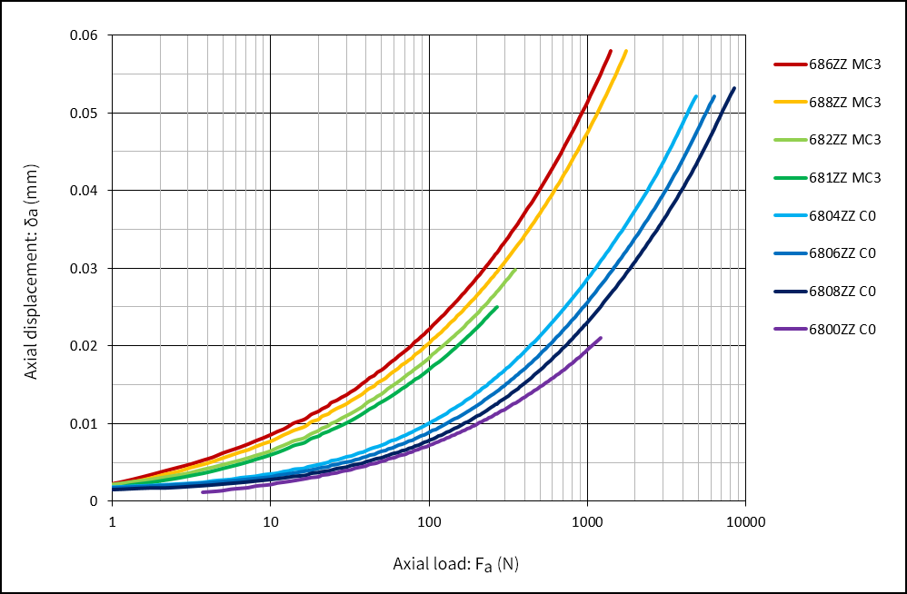
Axial load and axial displacement
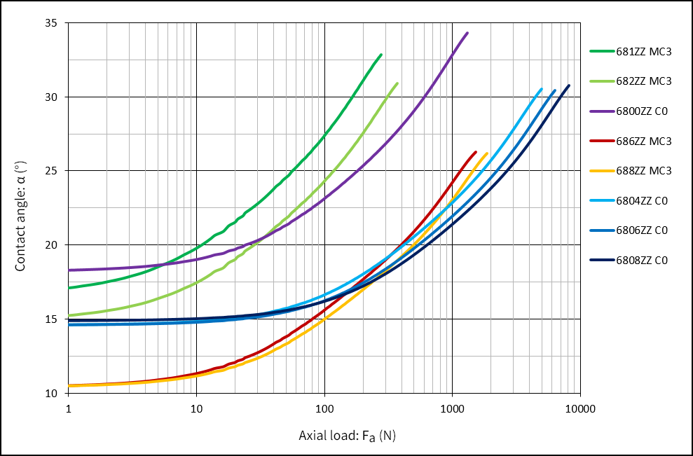
Axial load and change in contact angle
Radial Clearance and Bearing Fatigue Life
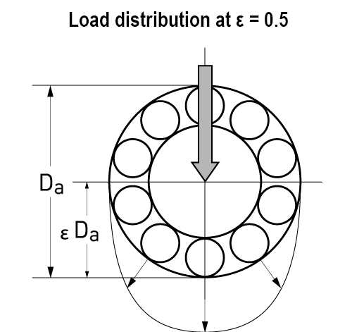
Normally, the radial clearance used for calculating the life of bearings is Δr = 0, where the load distribution within the bearing can be represented by a load factor of ε = 0.5. In this case, almost half of the balls receive the load. The load factor and the bearing fatigue life change based on the change of the radial clearance.
In the case of a deep groove ball bearing, the following relational equation is formulated between the radial clearance Δr and the load factor ε, and the function F(ε). Lε can be obtained from the relation between F(ε) and the life ratio Lε/L.
F(ε)=Δr×Dw(1/3)/(C×(Fr/Z)(2/3))
As shown in the example figure below, the longest life can be achieved when the clearance value is slightly negative. The figure also shows that as the clearance increases, the number of balls that receive the load decreases, which results in a shorter life.
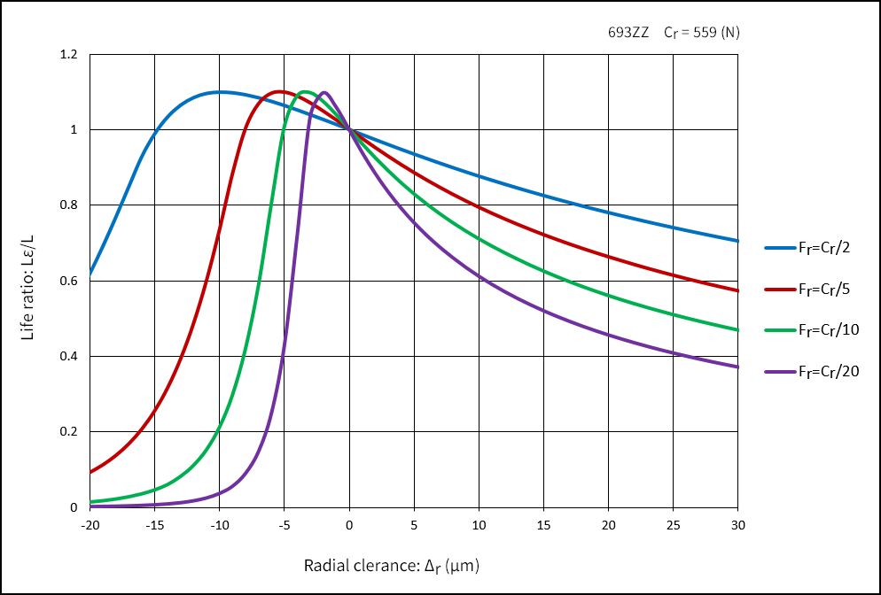
Radial clearance and bearing fatigue life
| ε | 0.1 | 0.2 | 0.3 | 0.4 | 0.5 | 0.6 | 0.7 | 0.8 | 0.9 | 1 |
|---|---|---|---|---|---|---|---|---|---|---|
| F(ε) | 33.7 | 10.2 | 4.05 | 1.41 | 0 | -0.86 | -1.44 | -1.86 | -2.2 | -2.49 |
| Lε/L | 0.29 | 0.55 | 0.74 | 0.89 | 1 | 1.07 | 1.1 | 1.09 | 1.04 | 0.95 |
| ε | 1.2 | 1.5 | 1.8 | 2 | 2.5 | 3 | 4 | 5 | 7 | 10 |
|---|---|---|---|---|---|---|---|---|---|---|
| F(ε) | -3.1 | -3.88 | -4.6 | -5.05 | -6.11 | -7.09 | -8.87 | -10.5 | -13.3 | -17.2 |
| Lε/L | 0.64 | 0.37 | 0.22 | 0.16 | 0.078 | 0.043 | 0.017 | 0.008 | 0.004 | 0.001 |