Products
- Home
- Products
- Product/technological information
- Life and Load Rating
Product/technological information
6. Life and Load Rating
Bearing Life
- The raceway and raceway surface of the inner/outer rings of the bearing continuously receive a repeated load, when rotated with a load applied. This causes material fatigue that results in a damage called flaking. The total rotational frequency to this point is called rolling fatigue life.
- The life of a bearing is based on a statistical value because there is a considerably large variation even though the same dimensions, material and heat treatment processing method are used to operate the bearing under the same conditions. Therefore, generally, the total rotating speed in which 90% of the bearings can be operated without the occurrence of flaking is called the basic rating life.
Basic Dynamic Load Rating
The basic dynamic load rating is the constant load applied in a direction under which the basic rating life of the bearing reaches 1 million revolutions. This is the centric radial load in radial bearings, and the centric axial load in thrust bearings. Also, for duplex bearings that consist of two single-row radial bearings with adjusted standouts, the basic dynamic load rating is converted by about 1.62 times that of a single-row bearing.
Life Equation
The relationships between the basic dynamic load rating, dynamic equivalent load, and the basic rating life of ball bearings are as follows.
| Total rotating speed | L10=(C/P)3×106 (Revolutions) |
|---|---|
| Operating hours | L10h=(C/P)3×16667/n (hours) |
| Distance | L10d=π×D×L10×10-6 (km) |
| Minimum basic dynamic load rating for operating conditions | Cmin=P×(L10h×n/16667)1/3 (N) |
L10h can be obtained by the following equation using life factor (fh) and speed factor (fn).
L10h=500×fh3、 fh=fn×C/P、 fn=(33.3/n)(1/3)
- L10=basic rating life (rev)
- L10h=basic rating life (h)
- L10d=basic rating life (km)
- P=dynamic equivalent load (N)
* Expressed as Pr in radial bearings and Pa in thrust bearings - C=basic dynamic load rating (N)
* Expressed as Cr in radial bearings and Ca in thrust bearings - Cmin=minimum basic dynamic load rating (N)
- n=rotating speed (min-1)
- D=rotating body outside diameter dimension (mm)
How to select basic rating life L10h
| Operating Conditions of a Machine | Basic rating life (h) L10h |
|---|---|
| In the case of low frequency of use | 500 |
| In the case of no great effect when a machine used for a short time or intermittently fails | 4,000~8,000 |
| In the case of great effect when a machine used intermittently fails | 8,000~12,000 |
| When a machine is used for 8 hours per day without being in full operation at all times | 12,000~20,000 |
| When a machine is operated full time 8 hours per day | 20,000~30,000 |
| When a machine is continuously operated 24 hours per day | 40,000~60,000 |
| When a machine is continuously operated 24 hours per day, and absolutely no stoppage due to failure is allowed | 100,000~200,000 |
Selection method of bearings in consideration of life for the operating conditions
When a large dynamic equivalent load P close to the basic dynamic load rating C is applied to a bearing, the bearing life is reduced in a very short time. However, when a bearing rotates at a high speed with high acceleration, or beyond the limiting speed x 0.5, it is necessary to set to P/C ≥ 1% in general, in order to prevent the occurrence of damage due to the sliding of the balls and the raceway surface.
A suitable bearing type must be selected based on Cmin = P×(L10h×n/16667)1/3 by clarifying the operating conditions of the machine (dynamic equivalent load P, rotating speed n) and the required lifetime L10h in advance.
As shown in the following table and graph, generally, it is necessary to consider selection of a bearing using [dynamic equivalent load] / [dynamic load rating] = P/C = [normal load ratio: 6 to 12%] as a guide.
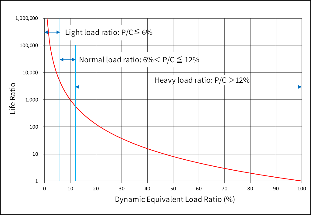
Dynamic Equivalent Load Ratio: P/C and Life Ratio
When P/C and n are known, rating life: L10h can be obtained easily using the following graph.
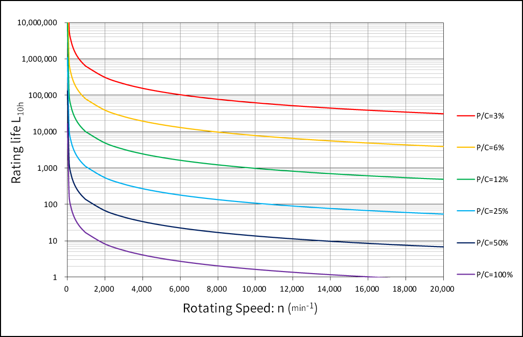
Dynamic Equivalent Load Ratio: P/C, Rotating Speed: n and Rating life: L10h
If P and n are known based on L10h= 50,000 hours as a reference, the minimum basic dynamic load rating: Cmin can be obtained easily using the following graph. It is recommended to select a bearing type with a basic dynamic load rating: C higher than this Cmin. However, rotating speed: n must not exceed the limiting speed of the selected bearing type.
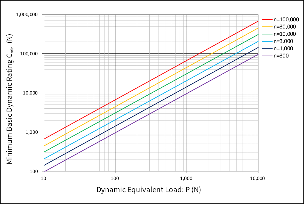
Dynamic Equivalent Load: P, Rotating Speed: n and Minimum Basic Dynamic Load Rating: Cmin
Modification of Life Equation
Generally, the life can be calculated by the above equation, however, it is insufficient when a high reliability of 90% or more is required depending on the application. Since the fatigue life of bearings has been prolonged due to improved bearing steel in recent years, and the relationship between the lubricant and the bearing life has also been clarified, the following modified life equation is used in ISO281.
Lna=a1×a2×a3×L10
Lna: Modified rating life [life when the level of reliability is based (100-n) %]
L10: Basic rating life (rev)
a1: Life modification factor for reliability
a2: Life modification factor for bearing characteristics
a3: Life modification factor for operating conditions
(1) Life modification factor for reliability a1
When calculating the life with a reliability of 90% or more, modify the value according to the following factor a1.
Values of life modification factor for reliability a1
| Reliability (%) | 90 | 95 | 96 | 97 | 98 | 99 | 99.2 | 99.4 | 99.6 | 99.8 | 99.9 | 99.92 | 99.94 | 99.95 | |
|---|---|---|---|---|---|---|---|---|---|---|---|---|---|---|---|
| Reliability Factor a1 | 1 | 0.64 | 0.55 | 0.47 | 0.37 | 0.25 | 0.22 | 0.19 | 0.16 | 0.12 | 0.093 | 0.087 | 0.08 | 0.077 | |
(2) Life modification factor for bearing characteristics a2
When the fatigue life is prolonged due to improvements in the manufacturing method and heat treatment condition, etc. of the bearing material, modify the value according to the life modification factor for bearing characteristics a2. In the case of the standard bearing material of our company, modify the value to a2=1.
(3) Life modification factor for operating conditions a3
In the operating conditions of a bearing, the modification factors which originate in the conditions of the lubrication, temperature and load, etc. is called “the life modification factor for operating conditions a3. In the case of favorable lubrication conditions, where there is no metal contact due to a lubricating film applied between the raceway surface and balls, and dynamic viscosity of lubricant is above 13 mm2/s(13cSt), then a3=1 is used for the effect of the lubrication on the life.
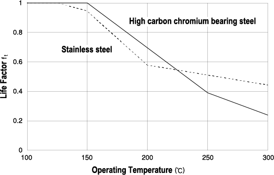
When the operating conditions are not favorable (dmn ≦ 10,000, deterioration of lubricant, large inclination of inner/outer rings), a3<1 is used. If the operating temperature exceeds 120 ºC, the life becomes shorter because the dimensional change becomes larger, and also the hardness deteriorates. The operating temperature and the life modification factor in such a case are based on the following table.
Remarks: dmn is the rolling element pitch circle diameter (mm) x rotating speed (min-1).
Value of temperature factor ft
Dimensional Stabilization Treatment
The dimensional change of a bearing with normal heat treatment applied becomes larger at temperatures exceeding 120 ºC. Although a reduction in the basic dynamic load rating due to the deterioration of the hardness is unavoidable, the dimensional change can be suppressed even at high temperatures by performing a dimensional stabilization treatment.
| Dimensional stabilization treatment symbol | S0 | S1 | S2 | S3 |
|---|---|---|---|---|
| Maximum operating temperature (ºC) | 150 | 200 | 250 | 300 |
System Life of Multiple Bearings
The basic rating life of each bearing has a probability of 90%. The system life of multiple bearings becomes even shorter than the shortest basic rating life of each bearing. Considering all the bearings being used as one bearing system, the system life can be obtained by the following equation.
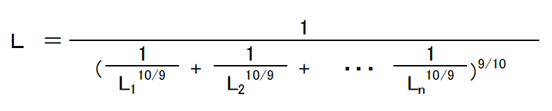
L=rating life of entire bearing system
L1、L2、L3・・・Ln=rating life of each bearing
Basic Static Load Rating
When a certain static load is applied to a bearing, a local permanent deformation of an indent shape occurs in the contact portion between the balls and raceway surface. This permanent deformation causes a poor rotating condition that also increases noise and vibrations, therefore, the basic static load rating Co is defined as follows as a reference of the acceptable static load. The basic static load rating of a ball bearing is the static load where the calculated contact stress becomes 4200 MPa(429kgf/mm2) in the contact portion between the balls and raceway, and the sum of the permanent deformation produced between the balls and raceway becomes about 1/10000 of the ball diameter. The value of the basic static load rating Co is expressed as Cor for radial bearings and Coa for thrust bearings. In addition, the Co of duplex bearings that consist of two single-row radial bearings with adjusted standouts is converted by twice that of a single-row bearing.
Calculation of Bearing Load
The loads applied to the bearings include drive loads, such as belts and gears, loads that occur in a machine during operation, and the self-weight of equipment supported by bearings. When a bearing is used, it is difficult to obtain the entire load accurately as the bearing load, because different levels of vibration and impact loads are applied. Normally, the load is obtained by multiplying the various factors based on the experience acquired conventionally with the calculated load value obtained theoretically.
(1) Load factor, gear factor and belt factor
The radial load and axial load applied to a bearing can be obtained by a theoretical calculation. However, the actually applied load becomes larger than the calculated value due to the vibration and impact of the equipment, therefore the load is obtained by multiplying the factors as follows.
| [Gear drive] | F=fw・fg・Fc |
|---|---|
| [Belt and chain drive] | F=fw・fb・Fc |
F: actually applied load (N)
Fc: theoretically calculated load (N)
fw: load factor
fg: gear factor
fb: belt factor
Load factor fw
| Operating Conditions | Examples | fw |
|---|---|---|
| No impact | Motors, machine tools, meters, conveyors | 1~1.2 |
| Light impact | Fans, cranes, compressors, pumps, elevators, paper-making machines | 1.2~1.5 |
| Strong impact | Rolling mills, crushers, drop hammers, vibrating filters | 1.5~3 |
Gear factor fg
| Type of Gears | fg |
|---|---|
| Precision gears [Pitch error ≦0.02mm, shape error ≦0.02mm] |
1.0~1.1 |
| Ordinary gears [Pitch error≦0.1mm, shape error ≦0.1mm] |
1.1~1.3 |
Belt factor fb
| Type of Belts | fb |
|---|---|
| Flat belts (without tension pulley) | 4.0~5.0 |
| Flat belts (with tension pulley) | 2.5~3.0 |
| V-belts | 2.0~2.5 |
| Toothed belts | 1.3~2.0 |
| Chains | 1.2~1.5 |
(2) Load distribution on bearings
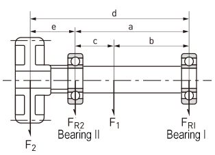
As shown in the figure, when radial loads F1 and F2 are applied, the load distributed on Bearing I and Bearing II can be obtained by the following equation.
FR1=c/a×F1-e/a×F2
FR2=b/a×F1+d/a×F2
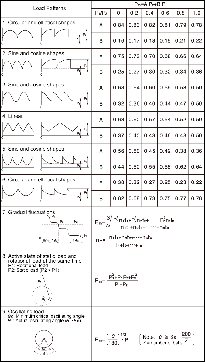
(3) Average load of fluctuating load
When the scale and direction of the load applied to a bearing fluctuates, it is necessary to obtain the average load so that it becomes equal to the bearing life under its loading condition.
Dynamic Equivalent Load
Although the load condition is not constant when a bearing is actually used, there are many cases where the load is a combination of the radial load and axial load. In such a case, it is necessary to calculate the load so that the direction and scale become constant. The calculated virtual load is called dynamic equivalent load P, and is expressed as Pr for radial bearings and Pa for thrust bearings.
(1) Radial bearings
| Bearing Types | Axial Load Ratio | Single-Row Bearings | Double-Row Bearings | e | ||||||||
|---|---|---|---|---|---|---|---|---|---|---|---|---|
 |
 |
|
|
|||||||||
| X | Y | X | Y | X | Y | X | Y | |||||
| Deep groove ball bearings |  |
1 | 0 | 0.56 | 1 | 0 | 0.56 | |||||
| 0.172 0.345 0.689 1.03 1.38 2.07 3.45 5.17 6.89 |
2.3 1.99 1.71 1.55 1.45 1.31 1.15 1.04 1 |
2.3 1.99 1.71 1.55 1.45 1.31 1.15 1.04 1 |
0.19 0.22 0.26 0.28 0.3 0.34 0.38 0.42 0.44 |
|||||||||
 |
1 | 0 | 0.56 | 1 | 0.78 | Single-row bearings | Double-row bearings | |||||
| Angular contact ball bearings | α=5° | 0.172 0.345 0.689 1.03 1.38 2.07 3.45 5.17 6.89 |
2.3 1.99 1.71 1.55 1.45 1.31 1.15 1.04 1 |
2.78 2.4 2.07 1.87 1.75 1.58 1.39 1.26 1.21 |
3.74 3.23 2.78 2.52 2.36 2.13 1.87 1.69 1.63 |
0.19 0.22 0.26 0.28 0.3 0.34 0.38 0.42 0.44 |
0.23 0.26 0.3 0.34 0.36 0.4 0.45 0.5 0.52 |
|||||
| α=10° | 0.172 0.345 0.689 1.03 1.38 2.07 3.45 5.17 6.89 |
1 | 0 | 0.46 | 1.88 1.71 1.52 1.41 1.34 1.23 1.1 1.01 1 |
1 | 2.18 1.98 1.76 1.63 1.55 1.42 1.27 1.17 1.16 |
0.75 | 3.06 2.78 2.47 2.29 2.18 2 1.79 1.64 1.63 |
0.29 0.32 0.36 0.38 0.4 0.44 0.49 0.54 0.54 |
||
| α=15° | 0.172 0.345 0.689 1.03 1.38 2.07 3.45 5.17 6.89 |
1 | 0 | 0.44 | 1.47 1.4 1.3 1.23 1.19 1.12 1.02 1 1 |
1 | 1.65 1.57 1.46 1.38 1.34 1.26 1.14 1.12 1.12 |
0.72 | 2.39 2.28 2.11 2 1.93 1.82 1.66 1.63 1.63 |
0.38 0.4 0.43 0.46 0.47 0.5 0.55 0.56 0.56 |
||
| α=20° α=25° α=30° α=35° α=40° α=45° |
― ― ― ― ― ― |
1 | 0 | 0.43 0.41 0.39 0.37 0.35 0.33 |
1 0.87 0.76 0.66 0.57 0.5 |
1 | 1.09 0.92 0.78 0.66 0.55 0.47 |
0.7 0.67 0.63 0.6 0.57 0.54 |
1.63 1.41 1.24 1.07 0.93 0.81 |
0.57 0.68 0.8 0.95 1.14 1.34 |
||
Dynamic equivalent radial load Pr of a radial bearing is expressed by the following equation.
Pr=dynamic equivalent radial load (N)
Fr=radial load (N)
Fa=axial load (N)
i=number of rows of balls
X=radial load factor
Y=axial load factor
Dw=ball diameter (mm)
Z=number of balls per row
(2) Thrust bearings
Dynamic equivalent axial load Pa of a thrust bearing is expressed by the following equation.
* Contact angle α of our thrust bearing is 90º.
Static Equivalent Load
The virtual load of the combination of the radial load and axial load that is received when the bearing is static (including very low speed rotations) which is calculated to ensure that the direction and scale become constant is called static equivalent load P0 and is expressed as P0r for radial bearings and P0a for thrust bearings.
The higher value of static equivalent radial load P0r of a radial bearing is used among the values calculated by the following two equations.
Static equivalent axial load P0a of a thrust bearing is expressed by the following equation.
* Contact angle α of our thrust bearing is 90º.
Safety Factor
The acceptable static equivalent load of a bearing is determined by the basic static load rating, however, the usage limitations of a bearing differ by the operating conditions and required performance. Therefore, in order to examine the safety integrity, the value can be calculated by the following equation using an experiential safety factor.
fs=Co/P0
fs=safety factor
Co=basic static load rating (N)
P0=static equivalent load (N)
| Operating Conditions | fs(min) |
|---|---|
| Normal operating conditions | 1.0 |
| Impact load | 1.5 |
| Quiet and high precision rotation is required | 2.0 |
Applied Calculation for Life and Load
Calculation Example 1
Assuming that the bearing bore diameter ≦ 10mm, outside diameter ≦ 20mm, and width ≦ 5mm are for the space to assemble a bearing, and the load condition is Fr (radial load) = 120 N and rotating speed n = 1200 min-1, select the type of single-row deep groove ball bearing with a life factor fh≧4.
Obtain speed factor fn as follows

If Cr is obtained from the equation  , the following equation holds:

Bearings with such a basic dynamic load rating selected from the dimensions table are as shown in the table below:
| Part No. | Bore Diameter (mm) | Outside Diameter (mm) | Width (mm) | Basic Dynamic Load Rating (N) |
|---|---|---|---|---|
| 625 | 5 | 16 | 5 | 1730 |
| 697 | 7 | 17 | 5 | 1610 |
| 6800 | 10 | 19 | 5 | 1720 |
Calculation Example 2
Select the bearing that has the smallest bore diameter, when selection conditions for the bearing are as follows: Material: SUJ2, Deep groove ball bearing: 60 series, Required life time: 10,000 hours or more, Radial load Fr=150N, Axial load Fa=20N, Rotating speed n = 5000 min-1.
Calculate Pr (the temporary dynamic equivalent radial load) as follows:

Since this is smaller than any "e" value in the table, the following equation can be considered: Pr=Fr=150N.
Obtain Cmin (the minimum basic dynamic load rating for operating conditions) as follows:

The bearing number with the smallest bore diameter whose Cr is 2163N or higher and the material is SUJ2 in the 60 series will be 606.
Calculate the value of Pr (dynamic equivalent radial load of 606), and check that the Pr obtained first (temporary dynamic equivalent radial load) is correct.
The axial load ratio of 606 is as follows:

From above, the following equation is obtained:

Thus, from , the equation
  is derived, which indicates that the temporary dynamic equivalent radial load obtained first is correct.
Calculation Example 3
What is the average radial load when the following variable radial load is applied?
P1=300N, n1=1800min-1, t1=10 (s)
P2=100N, n2=3000min-1, t2=15 (s)
P3=200N, n3=1000min-1, t3=20 (s)
Obtain Pm from Eq. (3) 7 of "Gradual fluctuations":

Calculation Example 4
What is the system life when the following radial rotational load and radial static load are applied to 6000HZZ, 6202HZZ and 6304HZZ?
| Part No. | Radial Rotational Load (N) | Radial Static Load (N) |
|---|---|---|
| 6000HZZ | 100 | 250 |
| 6202HZZ | 200 | 400 |
| 6304HZZ | 500 | 800 |
Obtain Pm from Eq. (3) 8 of "Active state of static load and rotational load at the same time," and L10 from the equation for "Life equation (operating hours)":
In the case of 6000HZZ:

As Cr of 6000HZZ is 3890N, the following equation holds:
 rotations:
L10=for the following also can be obtained in the same way:
| Part No. | Pm (N) | Cr (N) | L10 (rotation) |
|---|---|---|---|
| 6202HZZ | 467 | 6490 | 2684×106 |
| 6304HZZ | 992 | 13500 | 2520×106 |
Thus, the following is obtained from the equation for the system life of multiple bearings

Calculation Example 5
What is the lifetime L10h when radial load 150 N is applied to 688ZZ, and oscillates 1,000 time per minute at an oscillating angle of 30º?
688ZZ uses 10 φ2-mm balls. Cr is 1260N.


Obtain Pm from Eq. (3) 9 of "Oscillating load":

L10h is obtained from the equation for life equation (operating hours):

Calculation Example 6
What is the life time L10h, L1h where a stainless steel deep groove ball bearing 6706H 2RU is continuously operated at Radial load Fr = 100 N, Axial load Fa = 40 N, Speed n = 1800 min-1? Also, what is the grease life when 6706H 2RU is continuously operated at a bearing temperature of 80 ° C under the same conditions?
For 6706H 2RU: Cr = 969 N, and Cor = 757 N
Ball used: Dw = 1.588 mm, Z = 24 balls
According to the table of Dynamic Equivalent Load (Radial Bearings - factors X and Y of deep groove ball bearings) in this section, it becomes:


According to X = 0.56, Y = 1.733 and the equation of dynamic equivalent radial load, the following equation holds:

Therefore, the following is obtained from the equation for life equation (operating hours):

L1h can also be obtained as follows according to the reliability factor a1 = 0.25 when the reliability is 99%:

When general purpose grease is applied, the grease life can be obtained according to Eq. (8) of “9. Lubrication”:
