Products
- Home
- Products
- Product/technological information
- Fitting of Bearings
Product/technological information
7. Fitting of Bearings
The Importance of Fitting
The function of a bearing can only be utilized to the full when it is fitted appropriately to a shaft and a housing. If there is insufficient interference on the fitting surface, the ring will become misaligned in the circumferential direction to the shaft or the housing. This phenomenon is called “creep,” which may cause significant wear to the fitting surface, and damage the shaft or the housing. In some cases, this may even allow worn-off debris to enter the raceway, which may result in vibration and abnormal heating. In general, creep is generated on the ring where interference fit is used.
In order to prevent creep from taking place, necessary interference should be provided to the ring that receives the rotating load. Normally, interference is not provided to a ring that receives a static load. However, it is recommended to use an interference fit for both the inner and outer rings when using the bearing for applications subject to severe vibration.
| Rotating ring | Load | Load conditions | Fitting |
|---|---|---|---|
Inner ring |
Static |
Inner ring rotating load Outer ring static load |
Inner ring interference fit Outer ring clearance fit |
Outer ring |
Rotating |
||
Outer ring |
Static |
Outer ring rotating load Inner ring static load |
Inner ring clearance fit Outer ring interference fit |
Inner ring |
Rotating |
||
| When load direction changes or there is an unbalanced load | Rotating or static | Indeterminate direction load | Inner and outer rings interference fit |
Fitting between bearing and shaft
| Conditions (steel solid shaft) | Shaft diameter range | Shaft tolerance class | ||
|---|---|---|---|---|
| Thin-section | Other | |||
| Inner ring rotating load or indeterminate direction load | Light load of 0.06 Cr or less and fluctuating load | d≦18 18≦d≦30 30≦d≦50 |
h5 h5 h5 |
js5 js5 js5 |
| Normal load of 0.06 to 0.12 Cr | d≦18 18≦d≦30 30≦d≦50 |
js5 js5 js5 |
j5 k5 k5 |
|
| Outer ring rotating load | The inner ring must be able to travel over the shaft easily | Applicable to all shaft diameters | g5 | g6 |
| The inner ring does not have to travel over the shaft easily | Applicable to all shaft diameters | h5 | h6 | |
Fitting between bearing and housing
| Conditions(integrated housing) | Travel of outer ring in axial direction | Housing tolerance class | ||
|---|---|---|---|---|
| Thin-section | Other | |||
| Inner ring rotating load | Various loads | Can travel easily | H6 | H7 |
| Light or normal load | Can travel easily | H7 | H8 | |
| Temperatures of inner ring and shaft increase | Can travel easily | G6 | G7 | |
| Precise rotation in light or normal load required | Cannot travel in principle | K5 | K6 | |
| Can travel | JS6 | J6 | ||
| Quiet operation required | Can travel easily | H6 | H6 | |
| Indeterminate direction load | Light or normal load | Can travel normally | JS6 | J7 |
| Normal or heavy load | Cannot travel in principle | K5 | K7 | |
| Large impact load | Cannot travel | M5 | M7 | |
| Light or fluctuating load | Cannot travel | M5 | M7 | |
| Outer ring rotating load | Normal or heavy load | Cannot travel | N5 | N7 |
| Thin-section housing and heavy load or large impact load | Cannot travel | P6 | P7 | |
Fitting between miniature/small ball bearing (d < 10 mm) and shaft
| Load conditions | Bearing tolerance class | Single plane mean bore diameter deviation (Δdmp) | Dimensional tolerance of bearing diameter | Fitting | ||||
|---|---|---|---|---|---|---|---|---|
| Maximum | Minimum | Maximum | Minimum | Interference | Clearance | |||
| Inner ring rotating load | Mid to high speed Light to normal load |
A5P,A7P,P5 | 0 | -5 | +2.5 | -2.5 | 7.5 | 2.5 |
| P4 | 0 | -4 | +2.5 | -2.5 | 6.5 | 2.5 | ||
| Low speed Light load |
A5P,A7P,P5 | 0 | -5 | -2.5 | -7.5 | 2.5 | 7.5 | |
| P4 | 0 | -4 | -2.5 | -7.5 | 1.5 | 7.5 | ||
| Outer ring rotating load | Low to high speed Light load |
A5P、A7P、P5 | 0 | -5 | -2.5 | -7.5 | 2.5 | 7.5 |
| P4 | 0 | -4 | -2.5 | -7.5 | 1.5 | 7.5 | ||
Fitting between miniature/small ball bearing (d < 10 mm) and housing
| Load conditions | Bearing tolerance class | Single plane mean outside diameter deviation(ΔDmp) | Dimensional tolerance of housing bore diameter | Fitting | ||||
|---|---|---|---|---|---|---|---|---|
| Maximum | Minimum | Maximum | Minimum | Interference | Clearance | |||
| Inner ring rotating load | Mid to high speed Light to normal load |
A5P,A7P,P5(*1),P4(*2) | 0 | -5 | +5 | 0 | 0 | 10 |
| P5(18<D≦30) | 0 | -6 | +5 | 0 | 0 | 11 | ||
| P4(18≦D) | 0 | -4 | +5 | 0 | 0 | 9 | ||
| Low speed Light load |
A5P,A7P,P5(*1),P4(*2) | 0 | -5 | +2.5 | -2.5 | 2.5 | 7.5 | |
| P5(18<D≦30) | 0 | -6 | +2.5 | -2.5 | 2.5 | 8.5 | ||
| P4(18≦D) | 0 | -4 | +2.5 | -2.5 | 2.5 | 6.5 | ||
| Outer ring rotating load | Low to high speed Light load |
A5P,A7P,P5(*1),P4(*2) | 0 | -5 | +2.5 | -2.5 | 2.5 | 7.5 |
| P5(18<D≦30) | 0 | -6 | +2.5 | -2.5 | 2.5 | 8.5 | ||
| P4(18≦D) | 0 | -4 | +2.5 | -2.5 | 2.5 | 6.5 | ||
Note:
(1) applies to Class P5 (size: 18 ≦ D).
(2) applies to Class P4 (size: 18 < D ≦ 30).
Shaft dimensional tolerance
| Diameter classification | Δdmp(*) | d6 | e6 | f6 | g5 | h5 | h6 | h7 | h8 | h9 | h10 | js5 | js6 | j5 | j6 | j7 | k5 | k6 | k7 | m5 | m6 | n6 | p6 | r6 | r7 | |
|---|---|---|---|---|---|---|---|---|---|---|---|---|---|---|---|---|---|---|---|---|---|---|---|---|---|---|
| More than | Or less | |||||||||||||||||||||||||
| 3 | 6 | 0 -8 |
-30 -38 |
-20 -28 |
-10 -18 |
-4 -9 |
0 -5 |
0 -8 |
0 -12 |
0 -18 |
0 -30 |
0 -48 |
±2.5 | ±4 | +3 -2 |
+6 -2 |
+8 -4 |
+6 +1 |
+9 +1 |
+13 +1 |
+9 +4 |
+12 +4 |
+16 +8 |
+20 +12 |
+23 +15 |
+27 +15 |
| 6 | 10 | 0 -8 |
-40 -49 |
-25 -34 |
-13 -22 |
-5 -11 |
0 -6 |
0 -9 |
0 -15 |
0 -22 |
0 -36 |
0 -58 |
±3 | ±4.5 | +4 -2 |
+7 -2 |
+10 -5 |
+7 +1 |
+10 +1 |
+16 +1 |
+12 +6 |
+15 +6 |
+19 +10 |
+24 +15 |
+28 +19 |
+34 +19 |
| 10 | 18 | 0 -8 |
-50 -61 |
-32 -43 |
-16 -27 |
-6 -14 |
0 -8 |
0 -11 |
0 -18 |
0 -27 |
0 -43 |
0 -70 |
±4 | ±5.5 | +5 -3 |
+8 -3 |
+12 -6 |
+9 +1 |
+12 +1 |
+19 +1 |
+15 +7 |
+18 +7 |
+23 +12 |
+29 +18 |
+34 +23 |
+41 +23 |
| 18 | 30 | 0 -10 |
-65 -78 |
-40 -53 |
-20 -33 |
-7 -16 |
0 -9 |
0 -13 |
0 -21 |
0 -33 |
0 -52 |
0 -84 |
±4.5 | ±6.5 | +5 -4 |
+9 -4 |
+13 -8 |
+11 +2 |
+15 +2 |
+23 +2 |
+17 +8 |
+21 +8 |
+28 +15 |
+35 +22 |
+41 +28 |
+49 +28 |
| 30 | 50 | 0 -12 |
-80 -96 |
-50 -66 |
-25 -41 |
-9 -20 |
0 -11 |
0 -16 |
0 -25 |
0 -39 |
0 -62 |
0 -100 |
±5.5 | ±8 | +6 -5 |
+11 -5 |
+15 -10 |
+13 +2 |
+18 +2 |
+27 +2 |
+20 +9 |
+25 +9 |
+33 +17 |
+42 +26 |
+50 +34 |
+59 +34 |
Housing bore dimensional tolerance
| Diameter classification | ΔDmp(*) | E6 | F6 | F7 | G6 | G7 | H6 | H7 | H8 | J6 | J7 | JS6 | JS7 | K5 | K6 | K7 | M5 | M6 | M7 | N5 | N6 | N7 | P6 | P7 | |
|---|---|---|---|---|---|---|---|---|---|---|---|---|---|---|---|---|---|---|---|---|---|---|---|---|---|
| More than | Or less | ||||||||||||||||||||||||
| 10 | 18 | 0 -8 |
+43 +32 |
+27 +16 |
+34 +16 |
+17 +6 |
+24 +6 |
+11 0 |
+18 0 |
+27 0 |
+6 -5 |
+10 -8 |
±5.5 | ±9 | +2 -6 |
+2 -9 |
+6 -12 |
-4 -12 |
-4 -15 |
0 -18 |
-9 -17 |
-9 -20 |
-5 -23 |
-15 -26 |
-11 -29 |
| 18 | 30 | 0 -9 |
+53 +40 |
+33 +20 |
+41 +20 |
+20 +7 |
+28 +7 |
+13 0 |
+21 0 |
+33 0 |
+8 -5 |
+12 -9 |
±6.5 | ±10.5 | +1 -8 |
+2 -11 |
+6 -15 |
-5 -14 |
-4 -17 |
0 -21 |
-12 -21 |
-11 -24 |
-7 -28 |
-18 -31 |
-14 -35 |
| 30 | 50 | 0 -11 |
+66 +50 |
+41 +25 |
+50 +25 |
+25 +9 |
+34 +9 |
+16 0 |
+25 0 |
+39 0 |
+10 -6 |
+14 -11 |
±8 | ±12.5 | +2 -9 |
+3 -13 |
+7 -18 |
-5 -16 |
-4 -20 |
0 -25 |
-13 -24 |
-12 -28 |
-8 -33 |
-21 -37 |
-17 -42 |
| 50 | 80 | 0 -13 |
+79 +60 |
+49 +30 |
+60 +30 |
+29 +10 |
+40 +10 |
+19 0 |
+30 0 |
+46 0 |
+13 -6 |
+18 -12 |
±9.5 | ±15 | +3 -10 |
+4 -15 |
+9 -21 |
-6 -19 |
-5 -24 |
0 -30 |
-15 -28 |
-14 -33 |
-9 -39 |
-26 -45 |
-21 -51 |
Correlation diagram of shaft/housing and bearing

Calculating the Fit
The optimum fit should be selected for each application after considering a number of conditions such as the load size, rotation conditions, temperature conditions, and how the bearing is mounted/dismounted. Be sure to allow a greater interference than normal when a bearing is mounted on a thin housing, soft material, or a hollow shaft.
(1) Load size and interference
The interference between the shaft and the inner ring decreases when a radial load is applied. The amount of decrease can be obtained by the following equations, and the larger value should be adopted.
ΔdF=0.08× (d/B×Fr) 0.5/1000 (mm)
ΔdF=0.02×Fr/B/1000 (mm)
(2) Impact of temperature of bearing and shaft/housing
The operation of the bearing generates temperature differences among the bearing’s inner ring, outer ring, and balls, which cause a change in the interference with the shaft/housing. When the temperature difference between the bearing’s interior and around the housing is ΔT, the temperature difference between the shaft and the bearing’s fitting surface is assumed to be (0.1—0.15)×ΔT. Therefore, the amount of decrease of the inner ring’s interference at this temperature (ΔdT) can be obtained by the following equation:
ΔdT= (0.1~0.15) ×ΔT×a×d≒0.0015×ΔT×d/1000 (mm)
Conversely, the interference between the outer ring and the housing may increase due to differences in temperature and the rate of expansion. When using a housing material with a large coefficient of linear expansion, such as aluminum or zinc, typically the interference increases at a low temperature.
(3) Effective interference and finish of fitting surface
The roughness of a fitting surface is compressed due to fitting, resulting in smaller degree of effective interference than nominal. The amount of decrease from the nominal interference varies depending on how the fitting surface is finished. In general, however, the effective interference can be obtained by the following equations:
[Ground shaft] ... Δd=d/(d+2)×Δda (mm)
[Turned shaft] ... Δd=d/(d+3)×Δda (mm)
After merging the above equations, the nominal interference required for the inner ring and the shaft with inner ring rotating load can be obtained by the following equation:
Δda≧ (ΔdF+ΔdT) × ((d+3) /d or (d+2) /d) (mm)
(4) Surface pressure and maximum stress of fitting surface
If a bearing is mounted with interference, the ring will not break and remain secure provided the circumferential direction stress of the fitting surface is 120 MPa (12 kgf/mm2) or less.
| Surface pressure Pm (MPa) | |
|---|---|
| Shaft and inner ring | (Hollow shaft) Pm=(E×Δdb×(1-(d/db)2)×(1-(d0/d)2))/(2×d×(1-(d0/db)2)) (Solid shaft) Pm=E×Δdb/(2×d)×(1-(d/db)2) |
| Housing and outer ring | (Dh≠∞) Pm=(E×ΔDa×(1-(Da/D)2)×(1-(D/Dh)2))/(2×D×(1-(Da/Dh)2)) (Dh=∞) Pm=E×ΔDa/(2×D)×(1-(Da/D)2) |
| Circumferential direction stress δt(MPa) | |
| Shaft and inner ring | (Hollow shaft) δt=(E×Δdb×(1+(d/db)2)×(1-(d0/d)2))/(2×d×(1-(d0/db)2)) (Solid shaft) δt=E×Δdb/(2×d)×(1+(d/db)2) |
| Housing and outer ring | (Dh≠∞) δt=E×ΔDa×(1-(D/Dh)2)/(D×(1-(D/Dh)2)) (Dh=∞) δt=E×ΔDa/D |
(5) Press-in force and pull-out force
The press-in force and pull-out force can be obtained by the following equation based on surface area, surface pressure and the coefficient of friction of the fitting surface.
Kp=π×μ×Pm×B× (d or D) (N)
When the inner ring is pressed into the shaft, or when the outer ring is pressed into the housing ... μ=0.12
When the inner ring is pulled out from the shaft, or when the outer ring is pulled out from the housing ... μ=0.18
Meaning of symbols
- ΔdF=Amount of decreased interference due to load (mm)
- d=Nominal bearing bore diameter (mm)
- B=Nominal bearing width (mm)
- Fr=Radial load (N)
- ΔdT=Amount of decreased interference due to temperature difference (mm)
- ΔT=Temperature difference between bearing’s interior and around the housing (℃)
- a=Coefficient of linear expansion (1/℃)
- Δd=Effective interference (mm)
- Δda=Nominal interference (mm)
- E=Steel’s modulus of longitudinal elasticity=208000 (MPa)
- Cor=Basic static load rating (N)
- Δdb=Inner ring’s effective interference (mm)
- do=Hollow shaft’s bore diameter (mm); in the case of solid shaft do = 0 (mm)
- Da=Outer ring’s raceway diameter (mm); generally Da = (4×D+d)/5 (mm)
- D=Nominal bearing outer diameter (mm)
- Dh=Housing outer diameter (mm); for rigid body Dh=∞
- Kp=Press-in force or pull-out force (N)
- μ=Fitting surface’s coefficient of friction
- db=Inner ring’s raceway diameter (mm); generally db= (D+4×d)/5 (mm)
Figure 1 shows the minimum interference required to prevent the occurrence of creep for the radial load ratio (Fr/Cor), when a turned shaft is pressed into the extra-thin-section 67 series at ΔT=30℃.

Figure 1: Radial load ratio and required nominal interference
Figure 2 shows the relation between the effective interference and the circumferential direction stress of the fitting surface, when the 67 series’ inner ring is fitted with a solid shaft. The bearing will not break and will remain secure as long as the stress is σt < 120 (MPa). The points where each line graph intersects with the 120-MPa dashed line indicate the upper limit of effective interference.
Figure 3 shows the press-in force required under the same fitting conditions.
The pull-out force can be determined by multiplying the press-in force by 1.5.
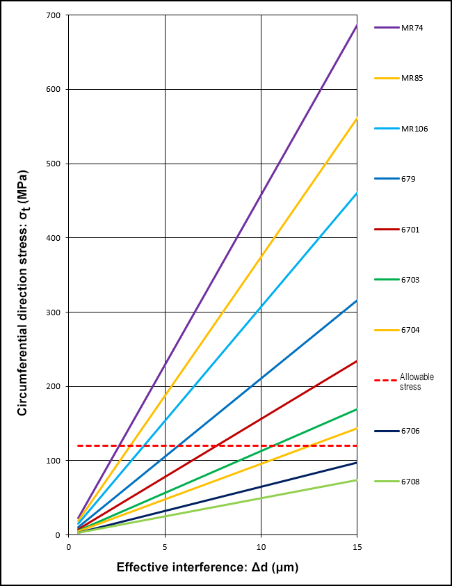
Figure 2: Effective interference and circumferential direction stress
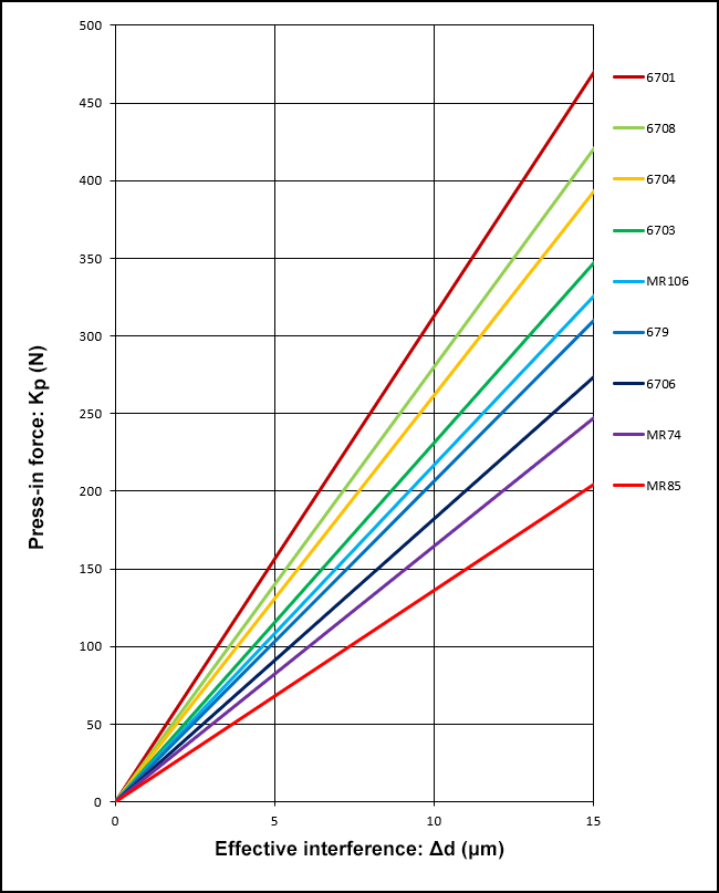
Figure 3: Effective interference and press-in force
* Pull-out force is determined by multiplying press-in force by 1.5
Precision and Roughness of Shaft and Housing
Normally, the shaft and the housing to be fitted to a bearing must satisfy the precision and surface roughness conditions below.
Recommended precision of shaft and housing
| Classification | Symbol | Shaft | Housing |
|---|---|---|---|
| Circularity |  |
Half or less of the shaft diameter tolerance | Half or less of the housing bore diameter tolerance |
| Cylindricity |  |
Half or less of the shaft diameter tolerance within the range of bearing width | Half or less of the housing bore diameter tolerance within the range of bearing width |
| Perpendicularity |  |
3/10000 (0.017°) or less | |
| Roughness of fitting surface | Ra | 0.8 | 1.6 |
Correspondence table of surface roughness values
| Arithmetic mean roughness (Ra) | Maximum section height (Rt) | Roughness no. | Triangle symbol |
|---|---|---|---|
| 0.025 | 0.15 | N1 | ▽▽▽▽ |
| 0.05 | 0.3 | N2 | |
| 0.1 | 0.6 | N3 | |
| 0.2 | 1.2 | N4 | |
| 0.4 | 2.4 | N5 | ▽▽▽ |
| 0.8 | 4.8 | N6 | |
| 1.6 | 9.6 | N7 | |
| 3.2 | 19 | N8 | ▽▽ |
| 6.3 | 38 | N9 | |
| 12.5 | 75 | N10 | ▽ |
| 25 | 150 | N11 | |
| (50) | (300) | N12 | |
| (100) | (600) | N13 |
Type and symbol of geometric tolerance
| Type | Symbol | |
|---|---|---|
| Shape | Straightness |  |
| Flatness |  |
|
| Circularity | |
|
| Cylindricity | |
|
| Line profile |  |
|
| Surface profile |  |
|
| Direction | Parallelism |  |
| Perpendicularity | |
|
| Inclination |  |
|
| Position | Positionality |  |
| Coaxiality |  |
|
| Symmetry |  |
|
| Swing |  |
|
Sort Categories of Bore/Outer Diameter Dimensions
For applications where an excess of or shortage of interference may become a problem, upon your request, we can deliver the products sorted into two categories each for bore and outer diameter dimensions, as shown below.

Remarks:
- Applied to P5, P4, ABEC5P, and ABEC7P bearings
- D=Lower limit of outer diameter dimensional tolerance
- d=Lower limit of bore diameter dimensional tolerance
- Let us know your requested details by selecting one option from below:
ZC1...Sort only bore diameter into two categories
ZC2...Sort only outer diameter into two categories
ZC3...Sort both bore and outer diameters into two categories